随着蜂窝行业不断向前发展,以满足更高的数据传输速率、更低的延迟和更高的可靠性的需求,射频系统设计再次成为任何蜂窝设备或网络的瓶颈,这些设备或网络的目标是在更苛刻的使用情况下为更多用户提供更多数据。
虽然
第三代合作伙伴项目(3GPP) 在不断发布更多规范以满足新需求并推动整个行业向 5G 时代迈进的同时,也出现了一些困惑和误解,使设备原始设备制造商对推出下一代 5G 产品的计划产生了怀疑。
天线设计是这一过程中最令人困惑的部分,因为它几乎完全取决于终端设备的外形尺寸和原始设备制造商的偏好。
Digi Wireless Design Services 从一开始就站在新兴技术的前沿。它在无线设备设计行业拥有众多合作伙伴,并在无线设备设计方面有着成功的记录。在本博客中,我们将就 5G 用户设备 (UE) 设备天线设计发表见解。
5G 新功能及其与当前 4G LTE 的区别
要理解 5G 能够提供比当前 4G 技术高得多的数据传输速率的原因,不妨先来看看香农-哈特里定理:
C = M * Blog2(1 + S/N)
- C 是信道容量,单位为比特/秒
- M 是通道数
- B 是每个通道的带宽
- S/N 是信噪比
实际上,要想获得更高的信道容量,就必须对系统的 M、B 和信噪比进行改进,这是一个直观的定理。从 4G 演进而来的 5G 在其架构中采用了一些众所周知且早已存在的技术,以提高其信道容量:
- 载波聚合 (CA)>增加带宽 (B)
- 多入多出架构 (MIMO)>增加信道数量 (M)
- 分配新频段>增加带宽 (B)
- 自适应采用高阶调制方案>S/N 和 B
与 4G 相比,5G 将同一套技术的能力和复杂性推向了新的高度。这不可避免地将 5G 设备的天线设计推向新的高度,以满足对更大带宽、更多频段和更好抗干扰性的不断增长的要求。
新的 5G 功能如何带来新的天线设计挑战
要为 5G 的功能规划和设计天线,就必须了解所面临的挑战以及如何应对这些挑战。 在此,我们将回顾这些考虑因素。
主动调谐天线系统
由于严格的尺寸限制,现代无线设备通常使用有源天线调谐器作为缩小天线尺寸的有效手段。它可以根据不断变化的工作环境、频段和带宽覆盖范围对天线进行智能调谐。随着 5G 和更多蜂窝频段中可能出现更高阶的 CA,天线调谐系统必须能够支持更多的调谐器状态以及每个调谐器状态更宽的频率带宽。
新频段
根据 3GPP Release 15,5G 将使用两个基本频率范围(FR1 和 FR2):
FR1:410 MHz 至 7.125 GHz;FR2:24.25 至 52.6 GHz
在 FR1 中,5G 在 4G LTE 现有的 3GHz 以下频段基础上,采用了 3.3 ~ 3.8、3.8 ~ 4.2 和 4.4 ~ 4.9 GHz 频段。这就对蜂窝天线提出了新的要求,以便在 6GHz 以下频率范围提供额外的频率覆盖。
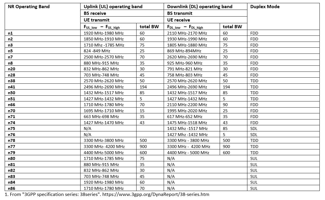
表 1:5G 新无线电(NR)在联邦登记处的运行频段1 1
FR2 或毫米波频率范围提供了极宽的带宽,在某些地区可达 2 GHz。要利用这一宽带宽的设备或系统,天线设计就必须有根本性的改变。由于信号传播损耗与信号波长成反比,毫米波信号会遭受严重的路径损耗。为了补偿路径损耗,通过设计相控阵天线来增加天线增益已成为业界公认的可靠解决方案。相控阵设计开辟了 4G 所没有的全新天线设计领域。
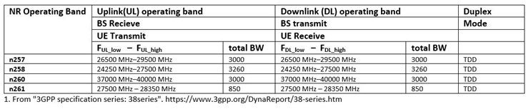
表 2:FR2 中的 5G 新无线电(NR)运行频段 1
天线系统设计因共存而面临挑战
MIMO 功能要求设备上同时存在多根天线,并在同一频段上运行。这项技术本身已经以 SU-MIMO 和 MU-MIMO(单用户 MIMO 和多用户 MIMO)的形式应用于 4G LTE 网络。
在 5G 中,Massive-MIMO(mMIMO)将成为将小区容量和 UE 下载数据速率提升到新水平的必要组成部分。虽然目前大多数 mMIMO 天线规格和技术评测都集中在基站侧,需要 32 个或更多的逻辑天线端口,但预计 UE 上的天线数量也会增加。
此外,由于 5G 启用了多重接入技术,蓝牙/WLAN、蜂窝等更频繁地同时在 UE 上传输,天线共存问题的解决只会更加复杂。如果处理不当,天线共存问题可能会导致通信范围缩小、出现意外盲点,甚至造成零星的连接质量下降。
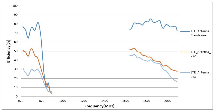
图 1 举例说明了共存导致的天线效率损失。必须在 5G UE 中战略性地布置天线,才能充分发挥多输入多输出(MIMO)的功效。
图 1:从 SISO 迁移到 MIMO 系统时天线效率的降低
应对 5G 天线设计新挑战的设计方法
既然我们已经介绍了一些挑战,那么让我们来讨论一些有助于确保成功的设计注意事项。
6 千兆赫以下天线设计方法
5G 天线按工作频率可分为两类:6GHz以下和毫米波。将 6GHz 以下 5G 与 LTE 4G 相比,系统射频前端和天线设计理念非常相似,唯一的区别在于横向复杂性。这意味着,从 4G 到 6 GHz 频段以下的 5G,系统侧将使用相同的组件,天线仍将是全向独立天线(与阵列天线相比)。
在这一频率范围内,偶极子天线、单极子天线、PIFA、IFA、环形天线等常见天线类型仍将像在 2G/3G/4G 中一样发挥主导作用。天线的外形尺寸多种多样,从简单的印刷迹线天线到复杂的激光直接成型(LDS)天线,不一而足。
更小的设备尺寸和更大的天线带宽要求之间的矛盾仍将是最大的挑战,只是比以前难得多。要解决这一日益激烈的矛盾,一个可行的办法就是设计有源天线系统。
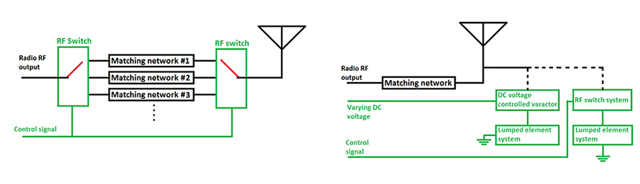
最常见的有源天线系统可分为两类:有源阻抗匹配和天线孔径调谐。有源阻抗匹配技术使天线系统能够根据工作条件的变化选择不同的阻抗匹配网络,而有源孔径调谐则直接改变天线的固有特性。
图 2:有源匹配(左)和有源孔径调谐图(右)
设备原始设备制造商也可以利用现成的 (OTS) 天线来简化天线设计流程。不过,与 4G 一样,相同的 OTS 安装在不同的设备上会有不同的表现,因为即使天线本身相同,不同的 PCB 也会提供不同的射频参考。OEM 至少需要为任何选定的 OTA 天线定制天线匹配网络。
毫米波天线设计方法
在毫米波频率上,信号传播路径损耗极大地限制了小区规模,带宽优势也会因连接覆盖问题而大打折扣。为了补偿信号路径损耗,相控阵天线因其能够实现极高的增益(dBi)而变得十分必要。
要为 5G 毫米波设计相控阵天线,需要大量有关天线设计基本概念、阵列天线设计实践、毫米波信号传播行为等方面的前期知识。 至少,相控阵天线应能引导和优化辐射波束,最大限度地将峰值 EIRP(dBm)传送到小区扇区内的移动接收设备。 为 5G 而精心设计的相控阵天线还应考虑到双极化、最小化阵列尺寸、降低侧叶电平、改善波束转向角范围和分辨率、抑制系统噪声、提高功率效率等因素。
毫米波天线测试也存在工程障碍。在这些高频率下,校准和设置会更加复杂,因为与 4G 频率相比,设置中的损耗会更加明显。保守估计,这种测试所需的资本设备投资可能超过 100 万美元。因此,选择一个了解规格和程序的测试合作伙伴就变得至关重要。
关于 Digi 无线设计服务
Digi Wireless 设计服务团队提供产品开发工程服务,帮助您为 5G 计划创建正确的解决方案。我们拥有丰富的经验、设备、基础设施和测试工具,可以帮助您设计出满足您需求的5G天线。如有任何疑问,请访问
Digi WDS 天线设计页面或
联系我们。
1 3GPP 规范系列:38 系列