

The i.MX6UL System-On-Chip has a lot of functionality but a limited number of pins (or pads). Even though a single pin can only perform one function at a time, they can be configured internally to perform different functions. This is called pin multiplexing.
The ConnectCore 6UL Hardware Reference Manual contains a Module pinout section that identifies all module pads with their corresponding signal name used in the reference boards schematics, and maps them to the corresponding i.MX pad name.
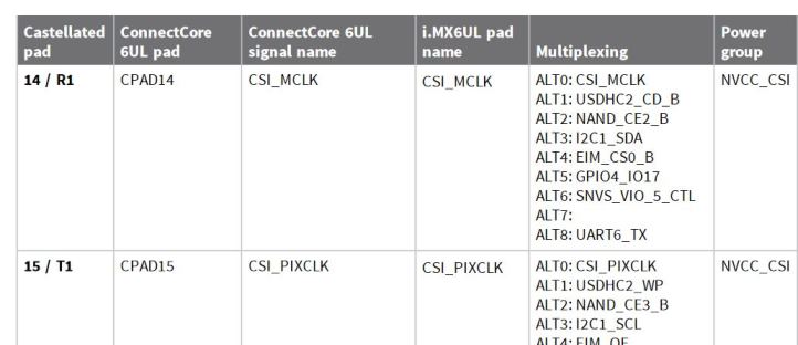
Pad multiplexing
The NXP i.MX6UL Reference Manual uses a pad name such as UART3_TX_DATA to refer to the System-On-Chip pads. This pad name typically corresponds to the first pad functionality. See the IOMUX Controller section of the NXP i.MX6UL Reference Manual for IOMUX configuration registers.
Electrical parameters of a pad
Every pad also has a PAD configuration control register where you can set the pad’s electrical parameters. See the NXP Influence of Pin Setting on System Function and Performance application note for details about setting functional and electrical parameters.
Use the device tree to configure pin IOMUX and pad control
Digi Embedded Yocto uses the Linux kernel device tree to configure the pad multiplexing and electrical characteristics for each of the reference boards. Customers designing their own boards will create a device tree matching their new board design and may need to configure the pads differently.
See Device tree files for an explanation of the Digi Embedded Yocto device tree structure.
The following example shows pad selection and IOMUX setting for a particular device: UART3. On the Linux kernel source, you can find the UART3 device tree node in arch/arm/boot/dts/imx6ul-ccimx6ulsbc.dtsi:
/* UART3 */
&uart3 {
    pinctrl-names = "default";
    pinctrl-0 = <&pinctrl_uart3_2wires>;
    status = "disabled";
};
The pin configuration is defined on the pinctrl-0 property, assigned the "default" name and set to pinctrl_uart3_2wires:
pinctrl_uart3_2wires: uart3grp_2wires {
    fsl,pins = <
        MX6UL_PAD_UART3_TX_DATA__UART3_DCE_TX   0x1b0b1
        MX6UL_PAD_UART3_RX_DATA__UART3_DCE_RX   0x1b0b1
    >;
};
The device tree pinctrl documentation binding explains the fsl,pins entry as consisting of six integers representing the IOMUX selection and electrical settings of the pin.
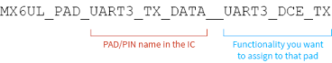
| You can look closely at the macro to discern how the pin name for the IC is connected to the desired pad functionality. From left to right, the part of the macro after the MX6UL_PAD_ prefix and up to the double underscore is the PAD/PIN name in the IC. In this example, it is UART3_TX_DATA. The second part (everything to the right of the double underscore) represents the functionality you would like to assign to that pad. |
The MX6UL_PAD_UART3_TX_DATA__UART3_DCE_TX macro defined in arch/arm/boot/dts/imx6ul-pinfunc.h contains five integers:
#define MX6UL_PAD_UART3_TX_DATA__UART3_DCE_TX 0x00A4 0x0330 0x0000 0x0 0x0
These five integers are:
-
IOMUX register offset (0x00A4)
-
Pad configuration register offset (0x0330)
-
Select input daisy chain register offset (0x0000)
-
IOMUX configuration setting (0x0)
-
Select input daisy chain setting (0x0)
The sixth integer, 0x1b0b1, corresponds to the configuration for the PAD control register. This number defines the low-level physical settings of the pin. You can build this integer using the information found in the device tree pinctrl documentation binding. You can also copy and then modify another pin definition that has similar functionality.
| Do not configure the same pad twice in the device tree. IOMUX configurations are set by the drivers in the order the kernel probes the configured device. If the same pad is configured differently by two drivers, the settings associated with the last-probed driver will fail to apply and the driver will not be brought up. |
