

The ConnectCore 6UL system-on-module contains an ultra-low power ARM Cortex-M0+ (NXP Kinetis KL03: KL03P24M48SF0) Micro Controller Assist chip.
Firmware update application
You can use the mca_fw_updater command line application to update the firmware that runs on the Micro Controller Assist (MCA) of the ConnectCore 6UL.
The flash memory of the MCA is divided into two regions: program flash and NVRAM. Before writing the new firmware, this application completely erases the contents of the program flash through the MCA bootloader. By default, the NVRAM is also erased.
| The MCA firmware is a critical part of the system. If you are not sure of the origin of your new firmware image or the benefits of updating it, do not proceed. |
| The bootloader must restart the MCA to re-run the application stored in flash, and this involves restarting the complete system. |
Check the latest MCA firmware version available
Your ConnectCore 6UL system-on-module ships from factory with a pre-programmed firmware on the MCA. Digi, however, ships fixes and updates of the MCA firmware on the support web site.
Digi recommends you verify the current firmware version of the MCA and check for a more recent version on the Digi support site.
Go to the ConnectCore 6UL software product page on the Digi web site to check for the latest available MCA firmware version.
Check the current MCA firmware version
Verify the current MCA firmware on your SOM by reading it on the U-Boot banner:
U-Boot dub-2020.04-r2.2 (Jan 18 2021 - 15:58:10 +0000)

CPU:   i.MX6UL rev1.2 528 MHz (running at 396 MHz)
CPU:   Industrial temperature grade (-40C to 105C) at 32C
Reset cause: POR
I2C:   ready
DRAM:  256 MiB
MCA:   HW_VER=1  FW_VER=1.19
PMIC:  PFUZE3000 DEV_ID=0x30 REV_ID=0x11
NAND:  256 MiB
MMC:   FSL_SDHC: 0
In:    serial
Out:   serial
Err:   serial
Model: Digi International ConnectCore 6UL SBC.
ConnectCore 6UL SOM variant 0x06: Industrial Ultralite 528MHz, 256MB NAND, 256MB DDR3, -40/+85C, Wireless, Bluetooth
  Board version 3, ID 135
Boot device:  NAND
Net:   FEC0 [PRIME]
Fastboot: Normal
Normal Boot
Hit any key to stop autoboot:  0
=>
On a running system, you can check the MCA firmware version by running the sysinfo command.
Compatibility with MCA firmware
-
ConnectCore 6UL SBC Express: all MCA firmware versions are supported.
-
ConnectCore 6UL SBC Pro: MCA firmware v0.12 or higher required. Previous versions are not supported and should be updated using a debugger. See Program MCA firmware.
Command line options
| Command line option | Action |
|---|---|
mca_fw_updater -v, --version |
Show the current version of the tool |
mca_fw_updater -h, --help |
Show the available options |
mca_fw_updater -f FILE, --file |
Erase the flash completely and update firmware with file FILE |
mca_fw_updater -f FILE -k, --keep-nvram |
Update firmware but keep current NVRAM contents |
Option -f erases both program and NVRAM flash sectors before installing the new firmware. If this option is used together with -k, the NVRAM will not be erased. Option -k alone is not valid; it performs no action.
Update MCA firmware
The firmware must be contained in a binary file, with read permissions for the user. When the program is invoked with option -f, it starts the update process:
~# mca_fw_updater -f mca_cc6ul_vX.XX.bin
The update process may take 20 seconds or more
During this process the chip drivers become unresponsive and you may
see I2C communication error messages on the console.
These error messages are expected and don’t interfere with the
firmware update process.
DO NOT POWER OFF OR RESET the device.
DO NOT CTRL+C OR ABORT this operation.
The program sends a message to the MCA firmware with the byte sequence for calling the bootloader and then checks that the bootloader is running. Then it performs the selected operations (update firmware, erase NVRAM). The process may take longer than 20 seconds, and the console displays a spinning bar. During this time, the system must be kept powered to successfully complete the update. Once the new firmware is written, resetting the MCA takes five seconds. Note that during the MCA reset process, the program appears to perform no action. The i.MX6UL CPU then reboots together with the MCA.
| Do not abort the firmware update process. If the process is interrupted during the write phase, the MCA could be left in an inconsistent state. If the process fails you can retry manually, but success is not guaranteed. In this case, you can only recover the MCA by flashing the firmware with a debugger probe. |
For more information about the mca_fw_updater application, see MCA management application.
Program firmware with JTAG debugger
| Digi recommends you use the mca_fw_updater application to update the MCA firmware, but you can also use a debugger. |
To program the MCA firmware using a JTAG debugger, you need:
-
A hardware debugger such as a P&E USB multilink debugger or a standalone Cyclone programmer.
-
An accessible Serial Wire Debug (SWD) port on your carrier board.
-
An adapter cable between the hardware debugger and the SWD port.
MCA SWD port
The Digi ConnectCore 6UL SBC Pro board has a tag connect footprint to access the SWD port of the MCA. Locate the SWD tag connect footprint on the labeled board image on the ConnectCore 6UL SBC Pro Hardware Resource Manual.
Use the following pinout as reference to create a custom cable between your debugger and the tag-connect footprint on the carrier board.
| Pin | Line |
|---|---|
1 |
VCC_MCA |
2 |
MCA_SWD_DIO |
3 |
GND |
4 |
MCA_SWD_CLK |
5 |
MCA_VCC |
6 |
- |
7 |
- |
8 |
- |
9 |
- |
10 |
MCA_RESET |

Use the pinout as reference to create a custom cable between your debugger and the tag-connect footprint on the carrier board.
Program firmware with USB multilink debugger
The P&E USB Multilink debugger is a hardware debugger that you can drive from a host computer via USB.
To program firmware using this debugger:
-
You need a GDB server running on the debugger. Download and install NXP Kinetis Design Studio, which contains a GDB server for the P&E multilink debugger.
-
Download the ELF image from the Digi product support page.
-
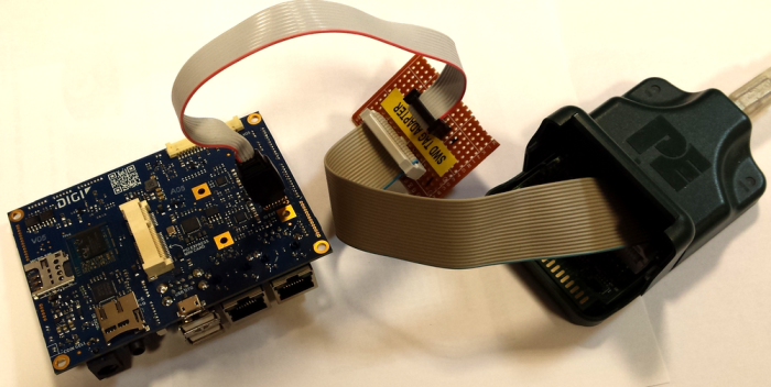
Connect the debugger to the PC via USB, and to the designated SWD port on the carrier board with the adapter cable. See SWD port for more information. You must hold the cable to keep it connected during the programming process. (The following image is included for general reference and may not match your board.)
-
Power on the board. Both LEDs on the debugger light up.
-
Run the Linux command line version of Kinetis Design Studio on your host computer with two parameters:
-
-startserver to start the P&E GDB server and
-
-device=<model> to specify the Kinetis model you are connecting to (NXP_KL1x_KL14Z32M4 for the I/O Expander, KL03: KL03P24M48SF0 for the MCA).
/opt/KDS_v3/eclipse/plugins/com.pemicro.debug.gdbjtag.pne_2.4.1.201603202153/lin/pegdbserver_console -startserver -device=<model>
The server runs, detects the hardware, and lists the ports it is running on.
-
-
In another shell, source the Digi Embedded Yocto SDK environment:
source /opt/dey/2.6-r3/ccimx6ulsbc/environment-setup-cortexa7t2hf-neon-dey-linux-gnueabi -
Run the GDB client:
arm-dey-linux-gnueabi-gdb -
At the GDB prompt, connect to the GDB server on the debugger (using one of the ports reported above):
target remote localhost:7224
The server reports "Connection from "127.0.0.1" via 127.0.0.1"
-
Load the ELF file you want to debug/program with:
load filename.elf
This erases and programs the flash and loads it with the file.
-
Continue execution of the loaded file with:
continue
-
Quit the GDB server by pressing CTRL+C.
-
The ELF file contains only the bootloader, not the full firmware. Once you install the bootloader, you can program the firmware using the application. See Update firmware.
-
When finished programming, restart to load the new firmware. Use the command sysinfo to print the firmware version and verify correct programming.
Program firmware with standalone Cyclone programmer
The P&E stand-alone Cyclone programmer is designed for programming in a production environment.
| The following instructions assume you have installed and configured your Cyclone programmer according to the manufacturer setup instructions. |
-
Download the desired SAP (Stand-Alone Programming) image from the Digi product support page.
-
Transfer the image to the Cyclone programmer. After this step is done, you no longer need the host PC and you can program the firmware with a button press.
-
On the Cyclone programmer, use the screen menus to select the image to program.
-
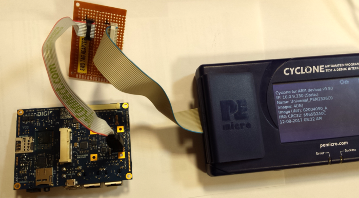
Connect the Cyclone programmer to the designated SWD port on the carrier board with the adapter cable. See SWD port for more information. You must hold the cable to keep it connected during the programming process. (The following image is included for general reference and may not match your board.)
-
Power on the board.
-
Press the Start button on the Cyclone programmer and wait for the Success LED to light up.
-
When finished programming, restart the device to load the new firmware. Use the command sysinfo to print the firmware version and verify correct programming.
